The villains are communicating with their own proprietary file format. Figure out what it is.
$ nc proprietary.ctfcompetition.com 1337
We get a server that will talk to us on a port and a
flag.ctf file that’s definitely not a binary. It’s a black-box reversing
challenge! I was @-mentioned as the person who might want to due to
solving bananaScript (CSAW CTF Quals 2017) as a black box, although that
gave a binary that it was possible in theory to reverse. Here black-box
reversing is the only option.
For the first few lines of input that the server wants, it responds
with quite helpful error messages to help you appease it. If the first
line you give it is not P6, it complains:
$ nc proprietary.ctfcompetition.com 1337
blah
Expected P6 as the header
Or if the second line is not two space-separated positive integers:
$ nc proprietary.ctfcompetition.com 1337
P6
blah
Expected width and height
Or if the third line is not 255:
$ nc proprietary.ctfcompetition.com 1337
P6
1 1
blah
Expected 255
It also complains if you pass a nonpositive width or height with a less helpful and apparently misspelled error message, but this is not particularly relevant.
$ nc proprietary.ctfcompetition.com 1337
P6
0 0
255
Image to big
In any case, this format matches the PPM format, so it
looks like we’re sending it a PPM image, 3 bytes per pixel, and then
it’s converting it to the titular Proprietary Format and giving us back
the result, which always starts with GCTF. (I didn’t recognize the PPM
format exactly when I started the challenge, but the mention of “width”
and “height” and inclusion of the number 255 made me pretty sure it was
an image format anyway.) The provided flag.ctf attachment
also starts with GCTF, so we guess that the challenge is to
reverse-engineer how the proprietary image format works and then recover
the image from flag.ctf.
First Steps
Our first non-error interaction looks like this:
$ nc proprietary.ctfcompetition.com 1337
P6
1 1
255
ABC
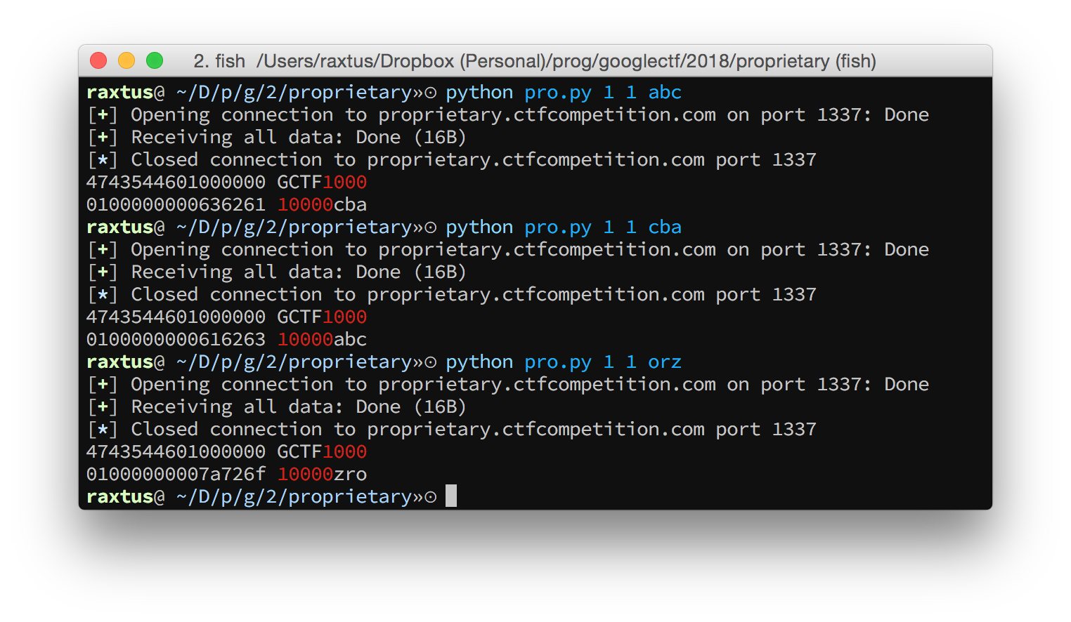
GCTFCBAHere we see that the three bytes we gave it, which we assume are the RGB components of a pixel, have been reversed. It’s pretty reasonable; it just means the bytes are being stored with the opposite endianness or something. In fact, we don’t really need to care too much about keeping the channels in order, since in the worst case we’ll get an image with color channels permuted, but any shapes and text will almost certainly still be legible.
Anyway, feeding the server characters by hand through nc
and manually observing results that look like the output I pasted above
is already inaccurate because we are already receiving null bytes and
other unprintable characters, so I switched to a pwntools
harness to print representations of these characters.
Probably the first thing I figured out through experimentation is the
header of the output, which is always 4 bytes that are always
GCTF, followed by 4 bytes that store the width in
little-endian format, followed by 4 bytes that store the height in
little-endian format. Then there’s data. In addition, all the remaining
bytes in the output are always either bytes we inputted or single
nybbles.
Because of this, I wrote a very simple hexdump function into my
harness with a terminal-color-coded side bar. In the side bar, printable
characters would be displayed normally, characters between 0 and 15
would be displayed as dim red hex digits, and everything else would just
be a magenta ?.
from __future__ import division, print_function
from pwn import *
import sys

def terminalify(c):
    if 32 <= ord(c) <= 126:
        return c
    if ord(c) < 16:
        return '\x1b[38;5;160m{:X}\x1b[0m'.format(ord(c))
    return '\x1b[35m?\x1b[0m'

def hexdump(s):
    for chunk in group(8, s):
        print((enhex(chunk).ljust(17) + ''.join(terminalify(c) for c in chunk)))

conn = remote('proprietary.ctfcompetition.com', 1337)
conn.sendline('P6')
conn.sendline(sys.argv[1] + ' ' + sys.argv[2])
conn.sendline('255')
conn.sendline(sys.argv[3])
conn.shutdown('send')
res = conn.recvall()
hexdump(res)
This script could be invoked like python pro.py 1 1 abc
to send a 1x1 image with pixel components taken from bytes in the string
"abc". I started out doing so, but for most of the later
experiments I just modified the script to put loop indices in the
args or manually specify a string with escaped characters
and reran it. We can run it a couple times just to verify the byte
reversal always happens.
An additional note: when pwntools is imported, it will
consume uppercase arguments from sys.argv and make them
available to you from its magic variable
args, so you can’t send strings of only uppercase
letters with this script.
Finally, it looks like the server always reads exactly \(3 \times h \times w\) bytes after the
255 and the newline. If we send more bytes, the server just
ignores them; if we send fewer, we get some random garbage from what is
presumably uninitialized memory. (If we knew this was the PPM format
we’d be sure of it too.)
At this point, it was time to start reverse engineering the rest of the bytes.
Width n, Height 1
The next thing I tried was changing my script to submit images with increasing width, but height fixed to 1, and an alphabet mash as the rest of the input. A pattern began to emerge.
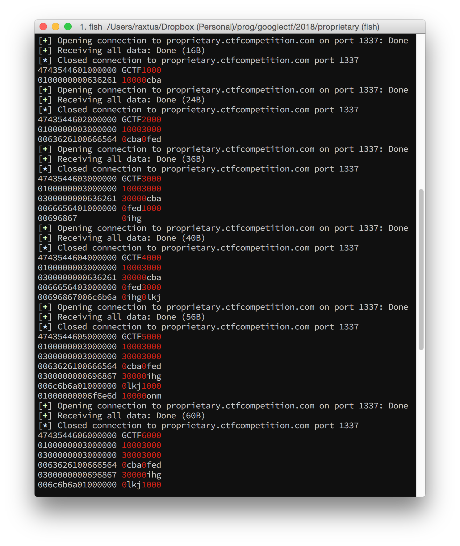
After the header, the bytes clearly formed 4-byte groups, and there were only three kinds of bytes:
- a zero byte followed by three inputted bytes,
- a 3 byte followed by three zero bytes, or
- a 1 byte followed by three zero bytes.
The inputted bytes also always came in order. I started tabulating these results with shorthand notation: Each whitespace-separated token would be a group of 4 bytes (“quad-bytes”). Digits and uppercase letters would represent single bytes less than 16 via hex digits, while lowercase letters would represent triplets of inputted bytes. Either component of a token could be omitted if it was 0. In this way, as I increased the width while keeping the height fixed to 1, I got these sequences:
GCTF 1 1 a
GCTF 2 1 3 a b
GCTF 3 1 3 3 a b 1 c
GCTF 4 1 3 3 a b 3 c d
GCTF 5 1 3 3 3 a b 3 c d 1 1 e
GCTF 6 1 3 3 3 a b 3 c d 1 3 e f
GCTF 7 1 3 3 3 a b 3 c d 3 3 e f 1 g
GCTF 8 1 3 3 3 a b 3 c d 3 3 e f 3 g h
GCTF 9 1 3 3 3 3 a b 3 c d 3 3 e f 3 g h 1 1 1 i
An example might make things clearer. The shorthand for the last line expands to these bytes:
47435446 ("GCTF")    09000000 (9: width)
01000000 (1: height) 03000000 (3)
03000000 (3)         03000000 (3)
03000000 (3)         00636261 (a: 0 followed by input bytes)
00666564 (b)         03000000 (3)
00696867 (c)         006c6b6a (d)
03000000 (3)         03000000 (3)
006f6e6d (e)         00727170 (f)
03000000 (3)         00757473 (g)
00787776 (h)         01000000 (1)
01000000 (1)         01000000 (1)
00617a79 (i)
After staring at this pattern for a while, particularly the patterns
from images where the width was a power of two in which no
1 tokens appeared at all, I figured out that I was looking
at was a preorder traversal of a more-or-less a binary tree with all
leaves at the same level.
- Quad-bytes consisting of a
3followed by three zero bytes represented nodes with two children; - quad-bytes consisting of a
1follwed by three zero bytes represented nodes with one child; - and quad-bytes consisting of a zero byte followed by three inputted bytes were leaves.
This made sense. By arranging the pixels in a row as leaves in a binary tree, if you then had a subtree where all leaf nodes had the same color, you could presumably represent the subtree differently so as to save space; it’s a classic strategy for range queries from competitive programming and definitely used in some image formats in the wild too. Of course, none of the nodes had any distinct representation here, but that also makes sense since all colors are distinct.
As an example, the last line represented this tree:
3
├─3
│ ├─3
│ │ ├─3
│ │ │ ├─a
│ │ │ └─b
│ │ └─3
│ │   ├─c
│ │   └─d
│ └─3
│   ├─3
│   │ ├─e
│   │ └─f
│   └─3
│     ├─g
│     └─h
└─1
  └─1
    └─1
      └─i
Or, with the tree drawn top-down:
       ┌────3───┐
       │        │
   ┌───3───┐    1
   │       │    │
 ┌─3─┐   ┌─3─┐  1
 │   │   │   │  │
┌3┐ ┌3┐ ┌3┐ ┌3┐ 1
│ │ │ │ │ │ │ │ │
a b c d e f g h i
I then tried again submitting images and increasing the width while
keeping the height fixed to 1, but this time, keeping all of my pixel
data identical — it was just the character a (or
0x61) over and over. In the same shorthand, these were my
results:
GCTF 2 1 Ca 0 0
GCTF 3 1 3 Ca 0 0 1 a
GCTF 4 1 3 Ca 0 0 Ca 0 0
GCTF 5 1 3 3 Ca 0 0 Ca 0 0 1 1 a
GCTF 6 1 3 3 Ca 0 0 Ca 0 0 1 Ca 0 0
GCTF 7 1 3 3 Ca 0 0 Ca 0 0 3 Ca 0 0 1 a
GCTF 8 1 3 3 Ca 0 0 Ca 0 0 3 Ca 0 0 Ca 0 0
GCTF 9 1 3 3 3 Ca 0 0 Ca 0 0 3 Ca 0 0 Ca 0 0 1 1 1 a
Again as an example, here’s the last line spelled out:
47435446 ("GCTF")    09000000 (9: width)
01000000 (1: height) 03000000 (3)
03000000 (3)         03000000 (3)
0c616161 (Ca)        00000000 (0)
00000000 (0)         0c616161 (Ca)
00000000 (0)         00000000 (0)
03000000 (3)         0c616161 (Ca)
00000000 (0)         00000000 (0)
0c616161 (Ca)        00000000 (0)
00000000 (0)         01000000 (1)
01000000 (1)         01000000 (1)
00616161 (a)
These are actually the same length as the outputs we got when
submitting all different pixels. So there’s no compression yet, which
makes understanding easier. The tree structure is still quite visible;
the only difference so far is in the leaf nodes and the nodes right
above them. If two leaf nodes with the same color have a parent node in
common, they are represented as Ca 0 0 instead of
3 a b.
I kept experimenting with these wide but short images with various patterns of equal and distinct colors, which more or less just continued to confirm the pattern above. It was time to move on to keeping the width fixed to 1, but increasing the height.
Width 1, Height n
Things did not go smoothly at first. Even when the height was only 2, my teammates and I were quite puzzled by the server’s behavior. When we passed, say,
P6
1 2
255
abcdef
to the server, the output would not contain the bytes corresponding
to the characters def. But if we submitted
P6
1 3
255
abcdefghi
then the output would contain the bytes corresponding to
characters ghi. We further observed that if we inserted a
newline among the second triplet of bytes, say,
P6
1 2
255
abcde<newline>
then the output would contain the bytes
<newline>ed. We thought for a while that we didn’t
understand the PPM format properly, and that somehow line breaks were
needed to reach a new row. However, this was disproved when I tried the
following, for which the output did not contain the bytes
f<newline>d.
P6
1 2
255
a<newline>cd<newline>f
Eventually I realized that what we were seeing was lossy compression
kicking in; the three bytes abc and the three bytes
def were too similar, and the server was compressing its
output in some sense by rounding the latter color to the former. On the
other hand, the codepoint of the newline character was sufficiently
different from all of these bytes, so that when we included one in the
second pixel, the algorithm no longer treated it as the same color as
the first pixel. But if I submitted a<newline>c and
d<newline>f, the algorithm went back to thinking they
were similar colors. To get more understandable behavior, all I had to
do was ensure that adjacent pixels were always highly distinct, for
example by setting one component of every other pixel to
\x00 and the same component in the other pixels to
\xff.
Once I did that, I could track the pattern in the same shorthand:
GCTF 1 1 a
GCTF 1 2 Ea 0 b 0
GCTF 1 3 5 Ea 0 b 0 1 c
GCTF 1 4 5 Ea 0 b 0 Ec 0 d 0
GCTF 1 5 5 5 a 0 b 0 Ec 0 d 0 1 1 e
GCTF 1 6 5 5 Ea 0 b 0 Ec 0 d 0 1 Ea 0 f 0
GCTF 1 7 5 5 Ea 0 b 0 Ec 0 d 0 5 Ee 0 f 0 1 g
GCTF 1 8 5 5 Ea 0 b 0 Ec 0 d 0 5 Ee 0 f 0 Eg 0 h 0
GCTF 1 9 5 5 5 Ea 0 b 0 Ec 0 d 0 5 Ee 0 f 0 Eg 0 h 0 1 1 1 i
There’s a binary tree structure just like before, but it’s a bit more complicated. Now, instead of 3’s, most of the time 5’s represent nodes with two children. The exception is at the layer right above the leaves, where E nodes appear instead. There, they directly contain an inputted pixel’s color in the same quad-byte, while the second inputted pixel follows it flanked by two all-zero quad-bytes. Because E nodes are followed by three quad-bytes instead of two, these representations are longer.
5
├─5
│ ├─5
│ │ ├─Ea
│ │ │ ├─0
│ │ │ ├─b
│ │ │ └─0
│ │ └─Ec
│ │   ├─0
│ │   ├─d
│ │   └─0
│ └─5
│   ├─Ee
│   │ ├─0
│   │ ├─f
│   │ └─0
│   └─Eg
│     ├─0
│     ├─h
│     └─0
└─1
  └─1
    └─1
      └─i
Or, with the tree drawn top-down:
           ┌──────5─────┐
           │            │
     ┌─────5─────┐      1
     │           │      │
  ┌──3──┐     ┌──5──┐   1
  │     │     │     │   │
┌─Ea┐ ┌─Ec┐ ┌─Ee┐ ┌─Eg┐ 1
│ │ │ │ │ │ │ │ │ │ │ │ │
0 b 0 0 d 0 0 f 0 0 h 0 i
And now, the same data collection with all identical colors:
GCTF 1 2 Aa 0 0
GCTF 1 3 5 Aa 0 0 1 a
GCTF 1 4 5 Aa 0 0 Aa 0 0
GCTF 1 5 5 5 Aa 0 0 Aa 0 0 1 1 a
GCTF 1 6 5 5 Aa 0 0 Aa 0 0 1 Aa 0 0
GCTF 1 7 5 5 Aa 0 0 Aa 0 0 5 Aa 0 0 1 a
GCTF 1 8 5 5 Aa 0 0 Aa 0 0 5 Aa 0 0 Aa 0 0
GCTF 1 9 5 5 5 Aa 0 0 Aa 0 0 5 Aa 0 0 Aa 0 0 1 1 1 a
This looks much more like the height-1 situation; the only change is that 3’s became 5’s and C’s became A’s, and of course that the dimensions were switched.
We haven’t even touched two-dimensional images yet, but already there’s a pretty strong pattern to be discovered from all our experiments so far.
The Common Pattern
For clarity, we will call the first byte in each quad-byte the
“node descriptor”. We’ve seen that node descriptor
1 represents nodes with one child, while node descriptors
3 and 5 both represent nodes with two
children. So do node descriptors A and C, more
or less, although thus far they’ve directly accompanied input bytes and
their leaf nodes have always been all-zero quad words. Node descriptor
E is a strange exception in that it also directly
accompanies input bytes, but is followed by three quad-bytes instead of
two, and of the three, two quad-bytes are all zero. Still, it makes the
most sense to think of node descriptor E as having three
children (which have always been leaf nodes in all the examples we’ve
seen so far).
What’s the pattern? It happens that when written in binary,
0x1 = 0b0001 has one bit set; 0x3 = 0b0011,
0x5 = 0b0101, 0xA = 0b1010, and
0xC = 0b1100 each have two bits set; and
0xE = 0b1110 has three bits set. Finally, all the leaf
nodes have been represented by quad-bytes starting with a 0
byte. If we think of 0 as the node decriptor, it has zero bits set, and
the leaf node of course has zero children.
So it seems that each quad-byte represents a node in a tree, the number of bits set in each node descriptor byte represents the number of children the node has in the tree, and that each quad-byte is followed by the recursively generated representations of the corresponding node’s children, if any. In pseudo-Python, the algorithm that parses the tree structure from the proprietary format looks like this:
def parse_node(stream):
    byte = stream.next()
    blue, green, red = stream.next(), stream.next(), stream.next()
    node = Node(color=(blue, green, red))
    for bit in byte.bits_set():
        node.add_child(parse_node(stream))
    return node
We can also reason about the spatial arrangement of the children of
each node. In our wide images, the parents were 3 = 0b0011
and C = 0b1100. It seems that when two leaves follow
3, they represent two horizontally adjacent pixels, and
when C directly accompanies a triplet of bytes, that color
is applied to two horizontally adjacent pixels. Since children are
represented by set bits, we guess that the bottom two bits represent
horizontally adjacent regions. Likewise, in our tall images, the parents
were 5 = 0b0101 and A = 0b1010. So we can
guess that the bottommost bit and the third bit from the bottom
represent vertically adjacent regions. So it seems that the four bits of
each node descriptor have some correspondence to a two-dimensional
layout, and then there’s only one logically place for the fourth bit to
go.
Pictorially, we conclude that the four bits w, x, y, z
of a node descriptor between 0 and 15 map to spatial regions this
way:
         ┌───┬───┐
         │ z │ y │
0bwxyz → ├───┼───┤
         │ x │ w │
         └───┴───┘
In this framework, we can now understand that:
- The number of children of each node is the number of bits in the node descriptor that are 1.
- Each node in our tree represents a square.
- The three color bytes directly after a node descriptor are the color of the quarters of the square whose corresponding bits in the node descriptor are 0.
- The four bytes are then followed by representations of all the node’s children.
Basically, it’s a quad tree!
We can confirm this by checking out what happens with a 2x2 image
with all pixels fairly distinct from each other. I sent the string
'a\0\0b\xff\xffc\xff\0d\0\xff'. The result is:
47435446 ("GCTF")    02000000 (2: width)
02000000 (2: height) 0e000061 (Ea)
00ffff62 (b)         0000ff63 (c)
00ff0064 (d)
In our shorthand:
GCTF 2 2 Ea b c dHere the E node is itself labeled with the color of the
first pixel, and is followed by its three children, all leaves, labeled
with the other pixels in row-major order. Pretty good.
We’re almost ready to write a parser and solve the challenge. There
is one more wrinkle, which I think only appears in images that are at
least 3x3 in size. Here’s the result of sending the 3x3 image
'a\0\0b\0~c\0\xffd~\0e~\xfff\xff\xffg\xff\0h\xff~i\xff\xff',
which has nine fairly distinct colors for its nine pixels:
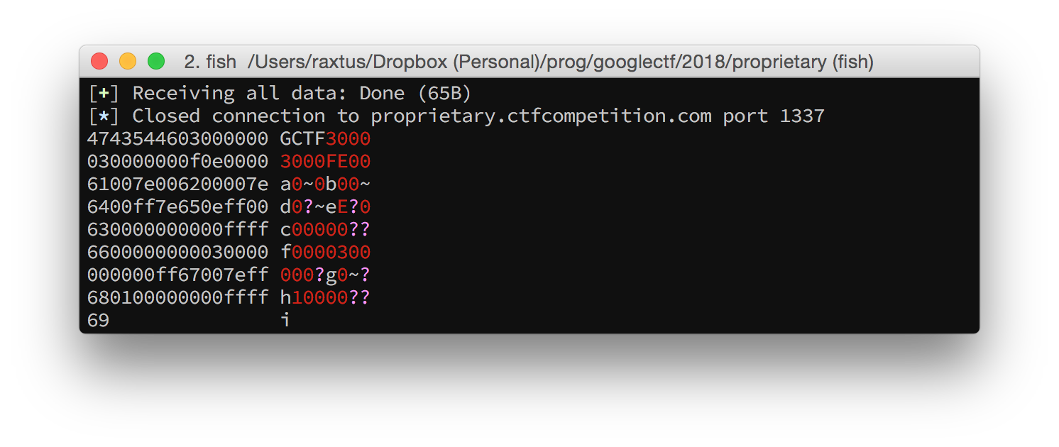
For the first time, we’ve encountered a case where the number of
bytes in the output isn’t divisible by four! Plus, our inputted color
bytes are all shifted away from where we expect them to be. What’s going
on? After a closer look, we quickly find that we can still recognize
parent and leaf nodes as we did before; the only difference is that
right after the header width and height, there’s an initial
0f byte that’s not followed by a triplet of color bytes.
This makes sense; since the 0f byte has all four bits set,
there’s no reason to specify a color after it, since that color wouldn’t
be applied to anything. Once we understand this, we can write down the
shorthand just as before, and the tree structure exactly matches what we
figured out earlier.
F
├─Ea
│ ├─b
│ ├─d
│ └─e
├─Ec
│ ├─0
│ ├─f
│ └─0
├─3
│ ├─g
│ └─h
└─1
  └─i
Top-down:
         F
  ┌─────┬┴───┬──┐
  │     │    │  │
┌─Ea┐ ┌─Ec┐ ┌3┐ 1
│ │ │ │ │ │ │ │ │
b d e 0 f 0 g h i
Or in the plane, where parenthesized colors are the ones specified in the parent node’s quad-byte:
F─────────┬─────────┐
│E───┬───┐│E───┬───┐│
││(a)│ b │││(c)│ 0 ││
│├───┼───┤│├───┼───┤│
││ d │ e │││ f │ 0 ││
│└───┴───┘│└───┴───┘│
├─────────┼─────────┤
│3───┬───┐│1───┬───┐│
││ g │ h │││ i │   ││
│├───┴───┤│├───┘   ││
││  (0)  │││    (0)││
│└───────┘│└───────┘│
└─────────┴─────────┘
In case you’re wondering, I made all the box-drawings-Unicode diagrams in this post manually in Vim with careful use of digraphs, copy-pasting, and blockwise Visual editing. It seemed like a good idea at the time.
Full Description and Solution
Now we can write down a pretty good description of the Proprietary Format.
The header consists of twelve bytes: the four bytes
GCTF, followed by four bytes for the width and four bytes for the height, both in little-endian.The rest of the data describes the image recursively as a tree structure. Each node represents a big square that’s part of the image. To parse a node from the stream of data and convert it to a square image S:
- Read the first “node descriptor” byte from the stream. Its value will be between 0 and 15. The four bits of this byte, from least significant to most significant, correspond to the four quarters of S: the top-left, top-right, bottom-left, and bottom-right in that order.
- If the node descriptor is not 15, read the next three bytes. They are the blue, green, and red components of the color of each quarter of S whose corresponding bit in the node descriptor is set to 0.
- Now, for each bit that is 1 in the node descriptor from least significant from most significant, parse a node from the stream, and convert that node to a square S’. The quarter square of S corresponding to that bit looks like S’.
The converted image will be a square. Its side length should be considered to be the smallest power of two that is greater than or equal to both the width and the height. Pixels outside the valid dimensions will have all components 0, i.e. be pure black.
Armed with this knowledge, we can write a final script to parse
flag.ctf back into a P6 ppm format, which can
be read by GIMP. Note that it doesn’t bother with figuring out the width
and height; for simplicity, I manually determined the flag image’s
dimensions to be 600x400 from looking at the header bytes, and hardcoded
the dimensions to be 1024, the next largest power of 2.
from __future__ import print_function
from pwn import *

def byte_stream():
    with open('flag.ctf', 'rb') as infile:
        infile.read(12) # header
        while True:
            s = infile.read(1)
            if s:
                yield ord(s)
            else:
                return

def solve():
    it = byte_stream()
    def go():
        sigil = it.next()
        color = (0, 0, 0)
        if sigil != 0xf:
            b = it.next()
            g = it.next()
            r = it.next()
            color = (r, g, b)
        if sigil == 0:
            return color
        return [
                go() if sigil & 1 else color,
                go() if sigil & 2 else color,
                go() if sigil & 4 else color,
                go() if sigil & 8 else color,
        ]
    bitmap = [[None] * 1024 for _ in range(1024)]
    def render(node, size, r, c):
        if isinstance(node, tuple):
            for i in range(2**size):
                for j in range(2**size):
                    bitmap[r + i][c + j] = node
        else:
            render(node[0], size - 1, r, c)
            render(node[1], size - 1, r, c + 2**(size - 1))
            render(node[2], size - 1, r + 2**(size - 1), c)
            render(node[3], size - 1, r + 2**(size - 1), c + 2**(size - 1))
    render(go(), 10, 0, 0)
    for row in bitmap:
        for color in row:
            for component in color:
                print(chr(component), end='')

print('P6')
print('1024 1024')
print('255')
solve()
Note that this only works in Python 2 because we are being lazy about tossing bytes, not text, into stdout. In Python 3 it’s probably simpler to write to a file opened in binary mode, or just write in a PPM format that takes decimal integers.
When the output is opened in GIMP and cropped to taste, we get this image, which reveals the flag:
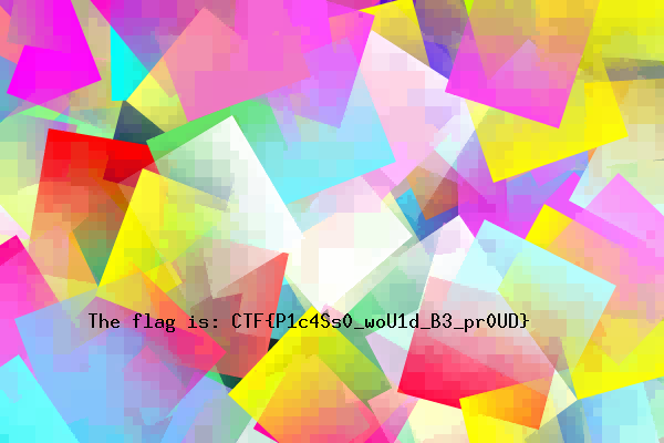
CTF{P1c4Ss0_woU1d_B3_pr0UD}